Guitars of Love
![]()
Building a superb, all discreet component, class 'A' DC coupled unbalanced to balanced DI box
|
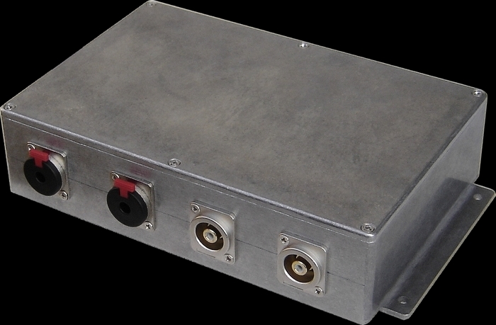
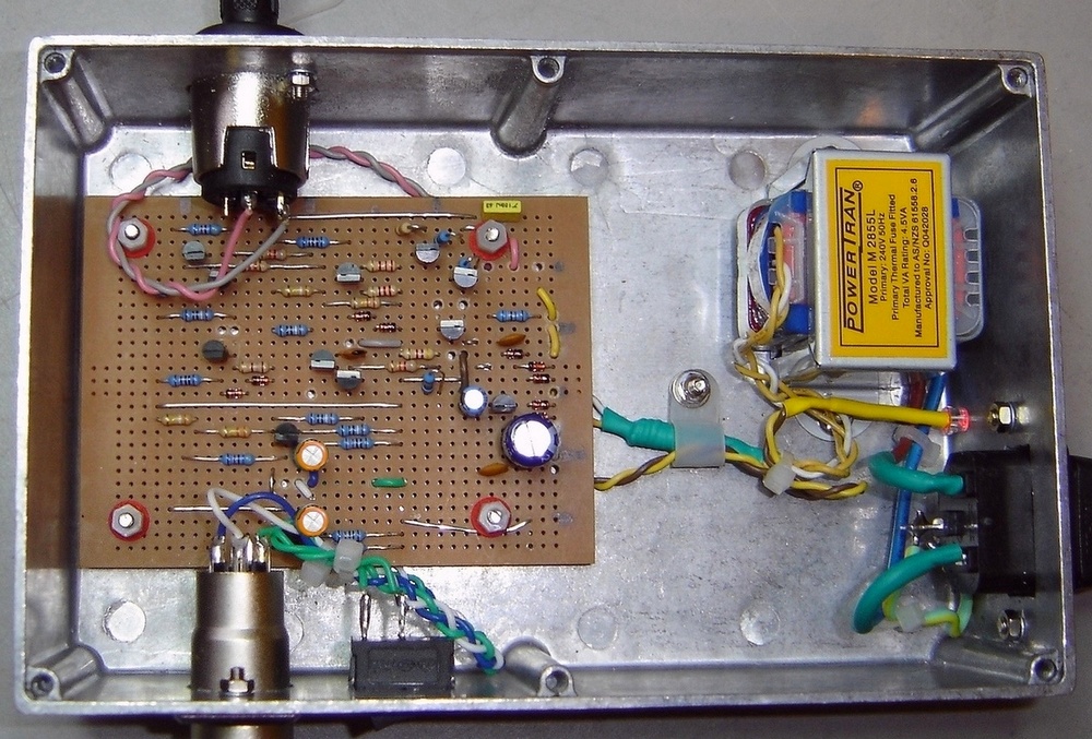
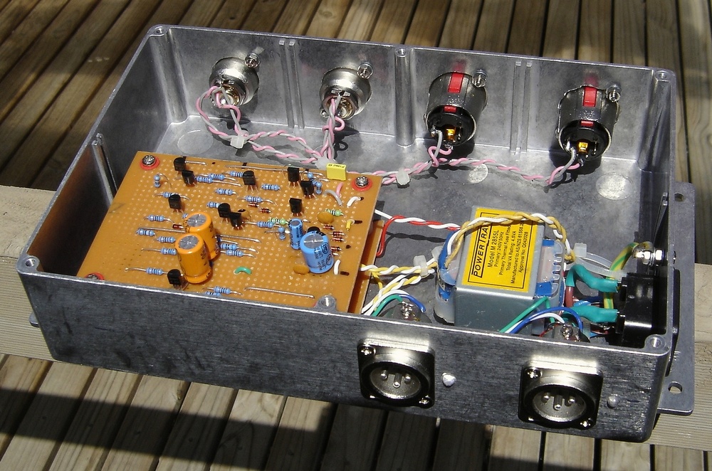
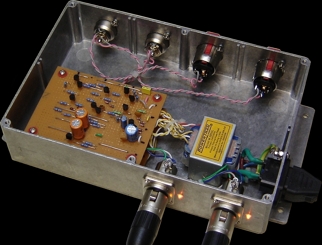
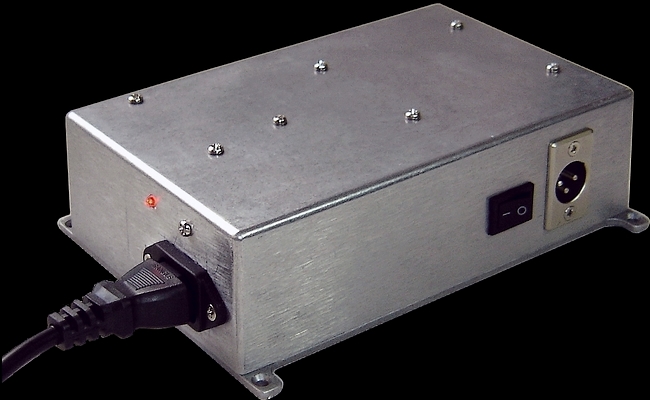
This project outlines an all discreet component device using class 'A' circuitry instead of a standard op-amp. It's too noisy to be useful with low level signals such as a microphone, but makes up for it by having a great warm punchy sound compared to a typical unit using ordinary op-amps. There are certain laws of physics I think that dictate that a small class 'B' push-pull amplifier which draws so little current such as a TL064 twin op-amp must suffer in the sound as a consequence. I had the idea for some time that this project would fill a niche in audio applications - or just the shear fun of it... It will not operate on phantom power at all however due to it's relatively high power consumption, which is around 35 - 40mA per channel. I also have a stereo version (Ch'A'/Ch'B') as in the right picture with twin phono and RCA input sockets, and twin XLR outputs. Coupled to the beefy Yamaha 2002 power amp, it sounds warm, silky and vibrant. It would be better with a toroidal power transformer however as there is a small amount of hum induction through the chassis due to the less than ideal layout in the alloy case.
|
Here is my stereo version |
|
Why are balanced lines
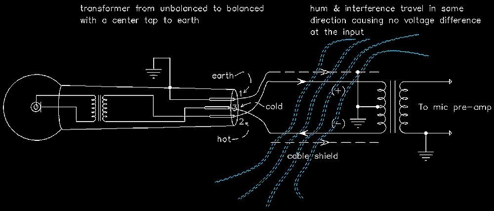
desirable in pro-audio? The great advantage of the balanced line is that any hum or noise introduced into the cables will be in the same phase, not + and - like the audio signals. When fed into the phase reversing input of a balanced system, they are effectively cancelled out. In most modern gear the centre tapped audio transformer which pioneered the technology in the '50s has been replaced with electronics such as op-amps with ( + ) & ( - ) inputs to create the 180 degree phase difference. Audio transformers to do the job of handling balanced signals are in the high end of mixers such as the APIs & Neves, due to their purity of sound. In audiophile circles, op-amps are frowned upon because they are essentually class B push-pull amplifiers which lack sonic purity. |
|
|
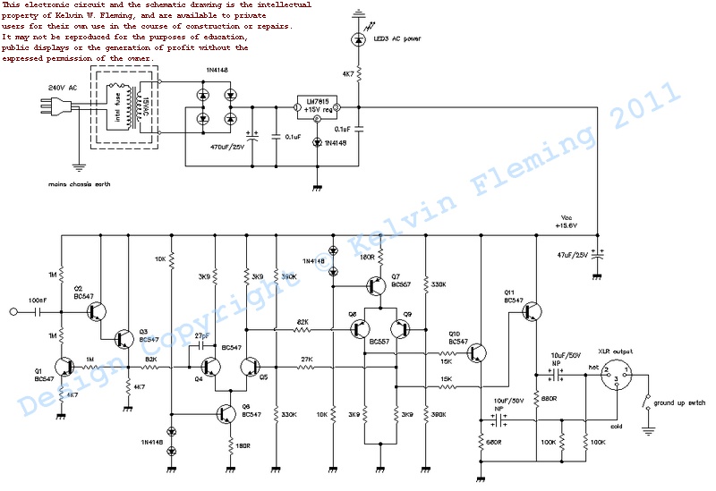
The DI described here has unity gain, and clips at 4.6 -> 5 VRMS so has enough head room for any audio application. It is all DC coupled apart from the input and output, and utilises about 28dB of negative feedback to control gain and noise. The frequency response is limited to about 50Khz by the little 27pF capacitor supplying negative feedback from the collector to the base on transistor Q4. It has an essentially flat response from 10Hz to 25Khz within + & - < 0.5dB. It features a hi-'Z' input which is good for guitar and bass, but is about +5dB noisier than a typical op-amp converter with a loaded input. In fact whereas an op-amp circuit increases in hiss when the input is loaded, this discreeet circuit decreases in noise significantly with a loaded input. See here for the DSO screen grabs of the unit in action.
|
|
At right is the 'schematic' for the circuit board inside the box which is built on vero board using my personal graphics technique. After the circuit has been tweaked on a breadboard and I am happy, I then design the vero board layout in full with a customised drawing program before going ahead and building it. I have done this for the last four or five projects and they have worked first time. Note: I have replaced the original LM78L15 (TO92 type) used on my prototype with the more bullet proof L7815 (TO220) +15 regulator. Click on the image at right for a the pdf schematic: |
|
|
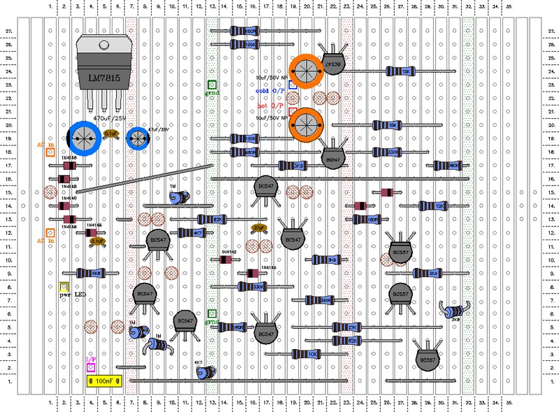
At right the vero board layout: The little brown circles represent the breaks in the copper which are scalloped out with a drill bit (see below...) to break the track in the right place to make the circuit work. The best way to locate them is to poke a piece of wire through the hole and turn the board over to see where to take make the break. Note: I have replaced the original LM78L15 (TO92 type) used on my prototype with the more bullet proof L7815 (TO220) +15 regulator. Please note that since building the original mono unit as shown, I have made a change to the output stage and replaced the straight links to the output buffers Q10 and Q11 with 15K resistors, and the emitter resistors from 3K9 to 680 ohms to give a standard audio O/P impedance. (The detailed pdf of the vero board layout opposite reflects this). The bipolar electrolytic capacitors at the output stage
are there to ensure that the device can handle systems with phantom
power. If ordinary polar caps are used they will short out due to
the positive voltage being greater on the -ive side of the cap than
the +ive side.
|
|
|
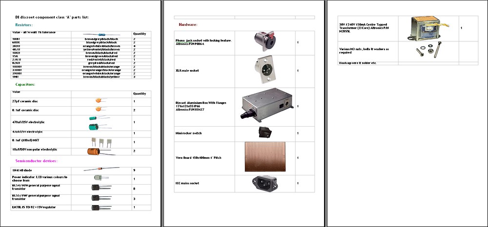
You can download a pdf document with the complete parts list with pictures. Just click on the image at right:
|
|
|
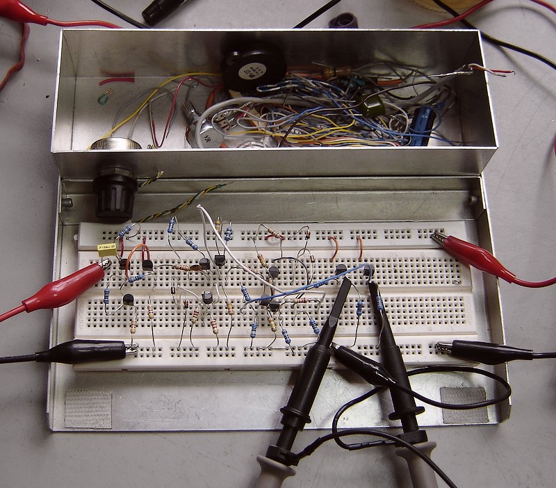
At right , testing and tweaking on the breadboard... |
|
|
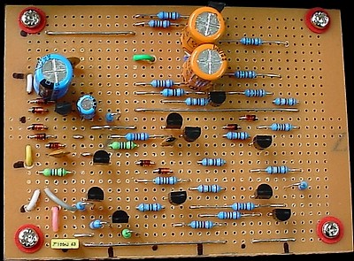
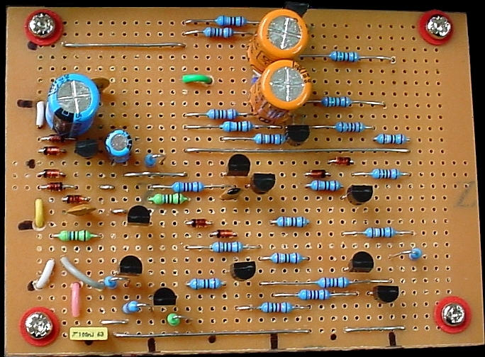
At right; detailed pictures of the vero board after parts have been soldered in place. The copper breaks are scalloped out with a 5/32 drill bit with a rubber band wrapped around as a handle.
All the hookup wires are threaded through the board by just drilling 1/16th holes where convenient (without disrupting the circuit) and feeding the wire up from the underside to the appropriate hole. This makes for highly reliable wiring. If the wires are just directly soldered in from the top they easily fatigue and break off whilst assembling. Many of the track breaking scallops can be used for this dual purpose.
|
|
|
| |
|
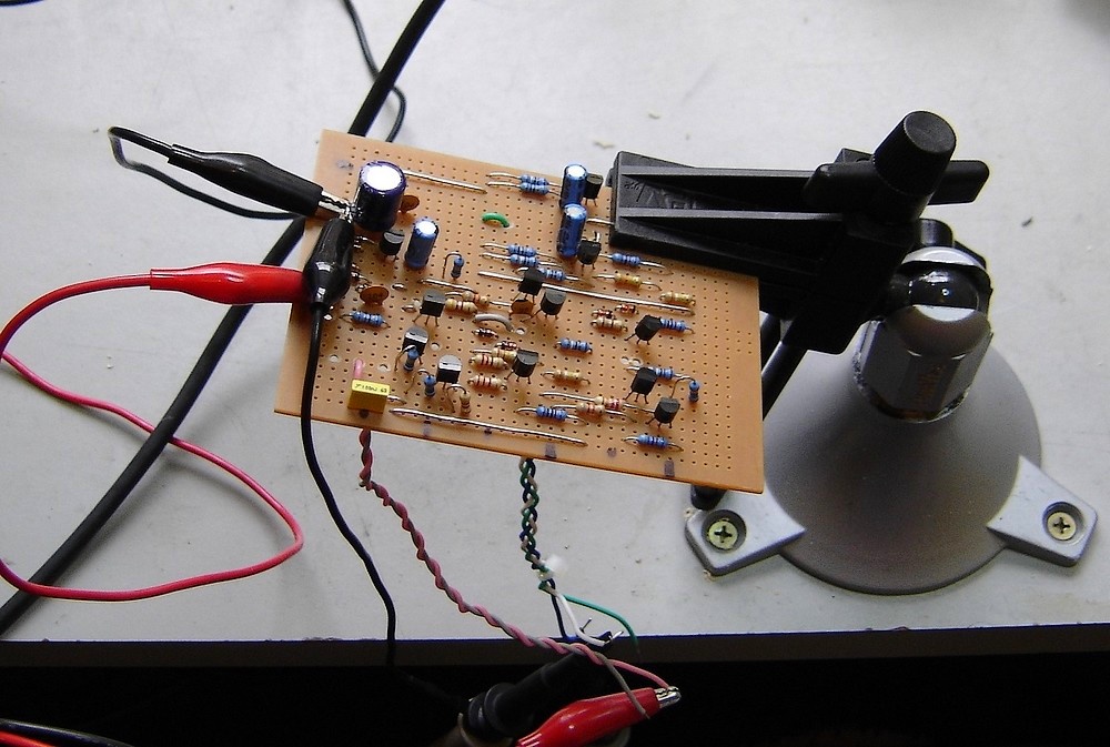
At right: testing the board on the signal generator and oscilloscope prior to installation - it worked first time :-) This board was my original version which had 3K9 output resistors on the output buffers Q10 and Q11. I have since changed these to 680 ohms with 15K resistors feeding the signal to the bases and if anything it works better. |
|
|
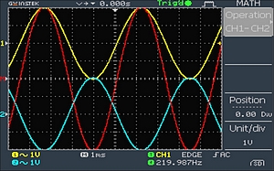
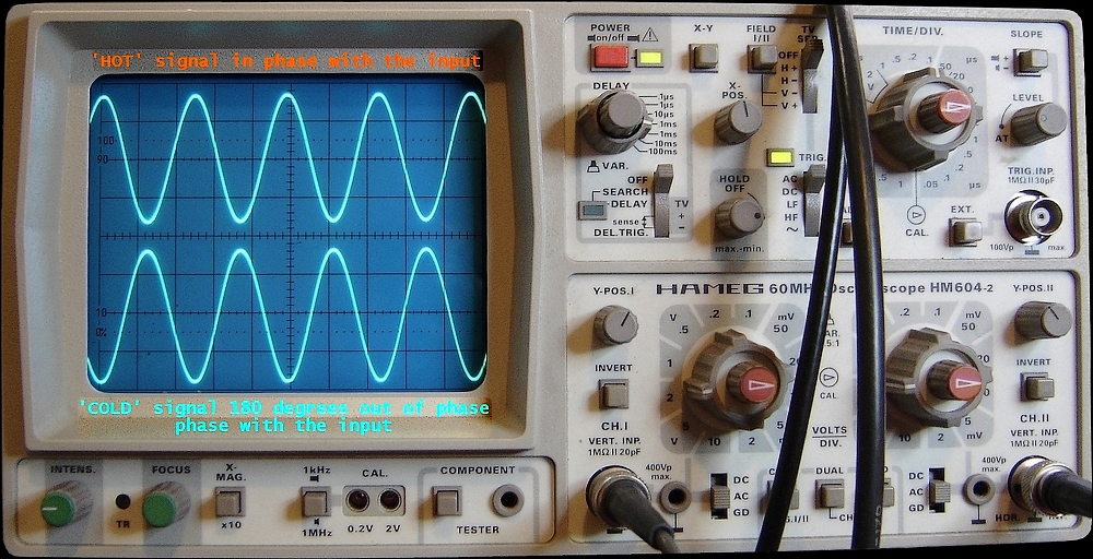
At right the CRO display showing the two sine waves 180 degrees of phase difference. The top waveform is hot (in phase), the bottom 180 degs reversed (cold). When the two signals are received by a balanced input, the opposite process occurs, where the cold signal is inverted back in phase with the hot signal so that the 180 degrees of phase is cancelled and the two signals can be summed. When this occurs it produces twice the voltage swing which = 3dB. The great advantage of the balanced line is that any hum or noise introduced into the cables will be in the same phase, not + and - like the audio signals. When fed into the phase reversing input of a balanced system, any hum and noise in the lines is put 180 degrees out of phase effectively cancelling them out. It's a clever system. The DI described here has unity gain, and clips at 4.6 -> 5 VRMS (~ 13.5V pk-pk) between hot & cold, so has enough head room for any audio application. It is all DC coupled apart from the input and output, and utilises about 28dB of negative feedback to control gain and noise. The frequency response is limited to about 50Khz by the little 27pF capacitor supplying negative feedback from the collector to the base on transistor Q4. It has an essentially flat response from 10Hz to 25Khz within + & - < 0.5dB. It features a hi-'Z' input which is good for guitar and bass, but is about +5dB noisier than a typical op-amp converter with a loaded input. In fact whereas an op-amp circuit increases in hiss when the input is loaded, this discreeet circuit decreases in noise significantly with a loaded input. |
|
|
|
|
|
|
|
| kelvin@guitars-of-love.com |
