Guitars of Love
![]()
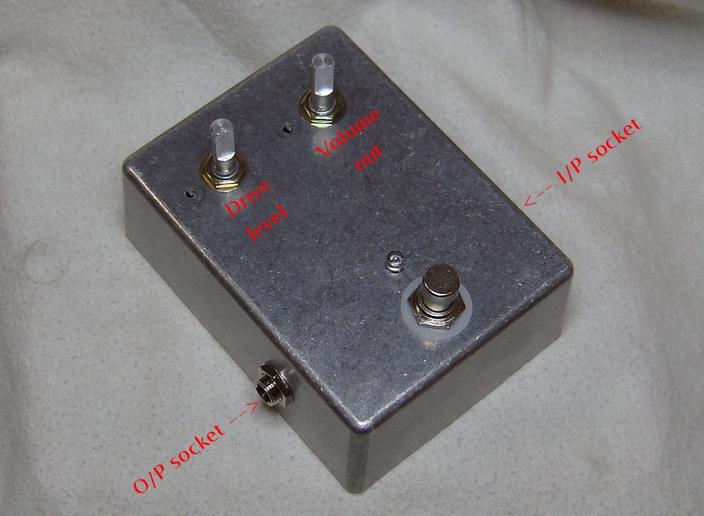
Building a 'DOD OD-250' preamp / overdrive pedal
 |

|
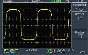
Click here for oscilloscope screen grabs of the OD pedal in action.
|
This is a really good project for anyone wanting a basic
great sounding overdrive pedal. The circuit is simple, and has a
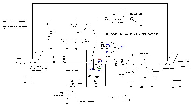
true bypass foot switch to maintain tonal integrity when not used. It's one of the best and simplest OD pedals ever made. It has a warm tone, but cuts through with no flubby extraneous crap typical of many distortion pedals. It works by the output of the little 8 pin op-amp running into two "back-to-back" diodes which clip the signal when they turn on at about 0.6 volts. The action of this is smoothed a little by having a small capacitor, 'C6' (1 nano Farad) over the diodes so it is not too abrupt. This emulates the sound of a valve (tube) type circuit going from a gentle rounding off of the audio signal to an extreme "square wave" which has straight edges. Below is the schematic for the circuit board inside the pedal: Click on the image for the full res pdf:
|
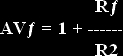
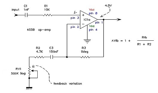
The gain of the circuit is controlled by the 500K pot which works by changing the negative feedback level ratio of 'R3' and 'R2' & 'RV1'. The formula for the gain of a non-inverting amplifier with -ve FB is is:
Consider 'R2' in the formula to be the combination of R2 in series with RV1. If you look at the above picture, the gain of the circuit at any time = 1+R3/(R2+RV1). When the gain is set at flat chat, RV1 will = 0, so the maximum gain will be 1+(1,000,000/4,700+0) because RV1 will be = 0. This gives a voltage gain of 212 times which = 46.5dB.
|
What makes it really clever in that the capacitor 'C3' acts as a "high pass filter" in the feedback circuit such that there is more -ve feedback (and hence less gain) in the bottom end as the overall gain goes up. In other words, because C3 presents a higher impedance at the lower frequencies, the feedback ratio of R3, R2 & RV1 is effectively higher. From a guitar point of view, this has the effect of keeping the driving sounds more focused at high OD levels by including less bottom end in the signal. It takes the harmonics of the strings and gives them a warm driving valve-like sound without turning into a turgid durge. The formula for the impedance 'Xc' of C3 is defined by the little formula: ... where 'F' is the frequency, 'pi' is the usual 3.1416 etc, and 'C' is the value of the capacitor. So at (say) bottom 'A' string on the guitar, the fundamental tone is 110Hz, this gives C3 a value of 9,646 ohms. So the feedback circuit will reduce the gain of the op-amp at this frequency by about 6.5dB to an approximate figure of 100 or 40dB. The capacitor doesn't behave as a straight resistor however because it causes a phase change as well as resistance. When Xc =4K7, the phase difference will be 45 degrees, and the combination of C3 & R2 will be = 6,646 ohms. This occurs at 225Hz when Xc = 4,700 ohms. The reduction in gain at this "turnover" frequency will be about 3dB. At very low bass frequencies the the Xc of C3 will be so high that the -ve FB will cut all the gain severley. You can experiment with the value of C3 to give the DOD different characteristics. The larger it is, the more low tones will get through and distort. |
|
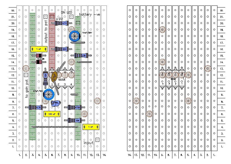
At right is the vero board layout: The right side is with the board flipped over. Click on the pic for the full res pdf. You can also download all the design criteria in one pdf document here:
|
|
|
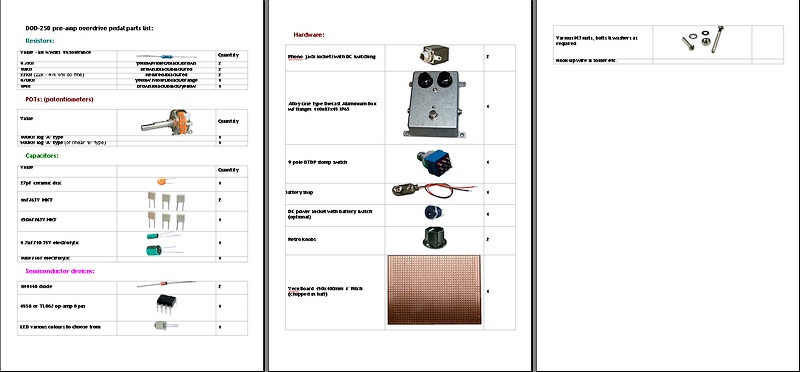
You can download a pdf of the the parts list with pictures. Just click on the pic at right: |
|
|
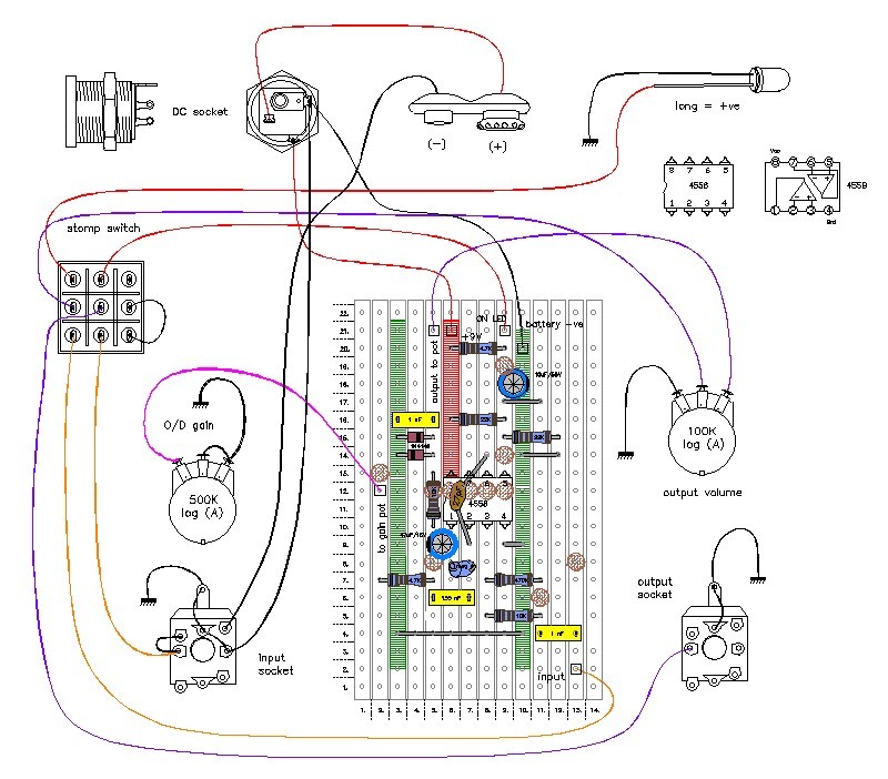
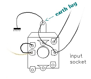
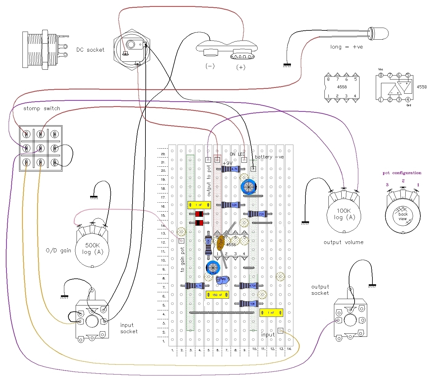
Wire-up drawing with the 9 pole stomp switch: Click on the image for the pdf: This shows exactly where to connect the wires in picture form to the various bits and pieces. NOTE: I have found the action of the gain pot (500K) to work best using a log (type 'A') pot, wired in reverse of the usual such that the gain increases when the knob is turned anticlockwise. This seems to suit the action of the pot better. This is shown looking at the rear of the pot. It may seem an odd arrangement but you get used to it. |
|
|
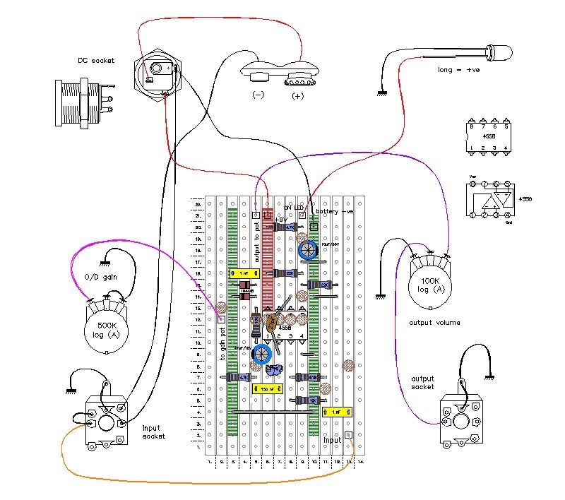
Wire-up drawing with no foot switch: |
|
|
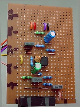
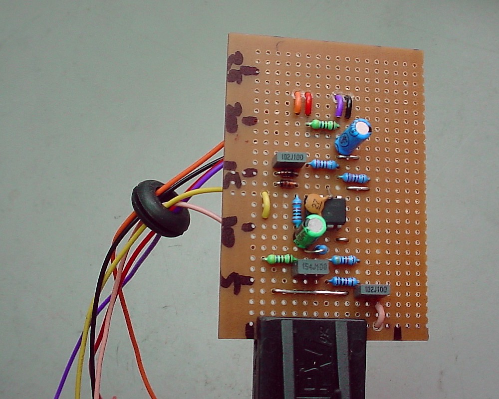
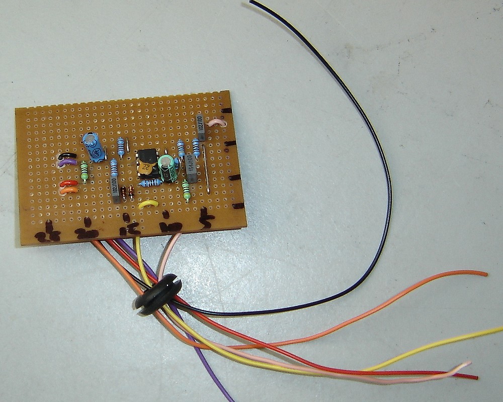
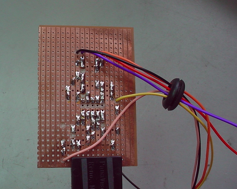
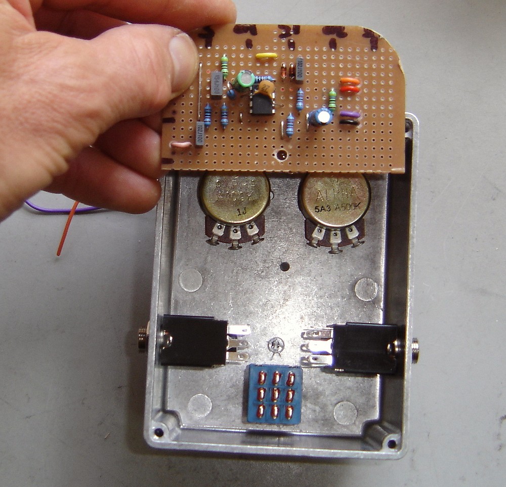
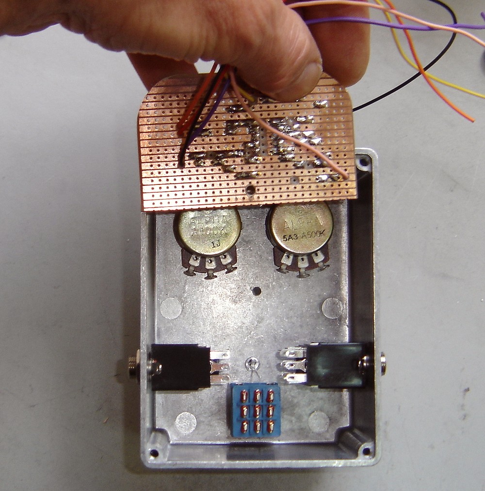
At right; detailed pictures of the vero board after parts soldered in place.
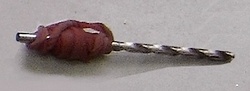
The copper breaks are scalloped out with a 5/32 drill bit with a rubber band wrapped around as a handle.
All the hookup wires are threaded through the board by just drilling 1/16th holes where convenient (without disrupting the circuit) and feeding the wire up from the underside to the appropriate hole. This makes for highly reliable wiring. If the wires are just directly soldered in from the top they easily fatigue and break off whilst assembling. Many of the track breaking scallops can be used for this dual purpose. |
|
|
| |
|
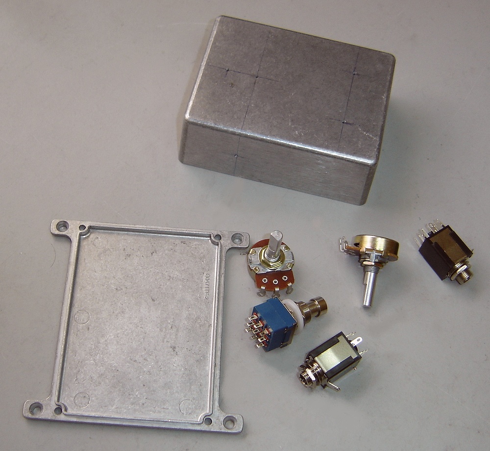
Basic hardware required:
|
|
|
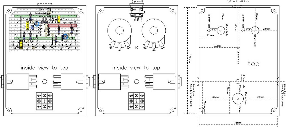
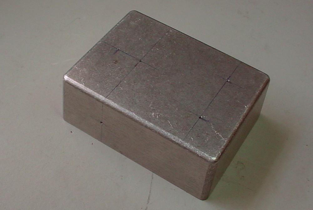
Case drill points marked out and drilled with small bit: |
|
|
The holes have been drilled out to size and parts are ready to go in. All hardware should be installed before wiring up commences. This way the appropriate lengths of hookup wire can be ascertained. It makes for a better layout. Note that the DC in socket needs to be slightly more than 1/2 way up towards the top so that the circuit board has clearance when being mounted. |
|
|
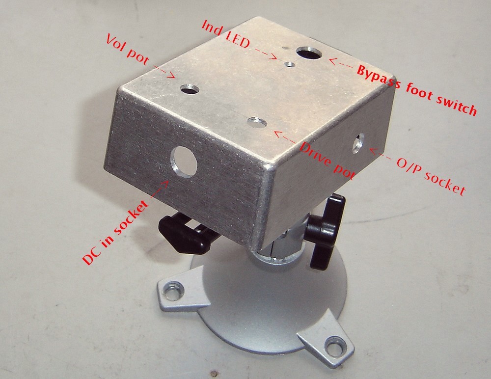
Now the hardware bits can be fitted... Make sure the jack sockets are installed with the earth lug pointing up towards you as in the diagrams.This allows the connections in the digram to make sense when you go to wire it up!
|
|
|
Top view... The pots (potentiometers) are anchored with a 1/8th drill hole positioned (see pic) to accommodate the little 'key' on the pot. This is easiest done by sighting where it will go and making a mark with a pen. This stops the pots from rotating when doing up the concentric nuts. The indicator LED is "interference fitted" by drilling a hole the size of the diameter of the LED and forcing it in. |
|
|
The 1/8th hole for the bolt which holds the circuit board in should be about 40mm down from the top end (pot end) of the case. Line up the circuit board as shown and mark with a 1/8th drill where the mounting hole will go. Enough room must be left so that the 9V battery can be slipped in and out. |
|
|
Make sure the the M3 bolt securing the circuit board in will not "short out" part of the circuit to earth. |
|
|
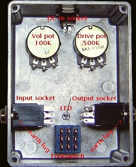
Next is the wiring up. The hookup wire can be shortened to appropriate lengths now. A visual representation the hookup layout is below or here. Note that the +ve lead from the indicator LED was able to be routed directly to the foot switch - just a bit of heatshrink over the lead to insulate. Also the circuit board mounting bolt now has a nylon M3 spacer/nut on it which allows the height of the board to be adjusted, and also insulates around the hole to avoid electrical contact. |
|
|
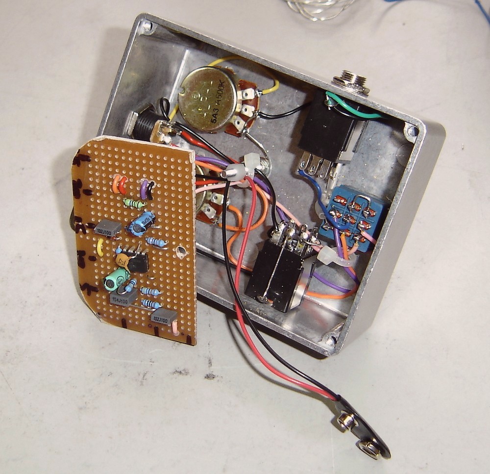
A couple of cable ties to tidy it all up.. Just keep the O/P wire separate from the input wire, as this can cause +ve feedback in the form of oscillation at high gain settings. |
|
|
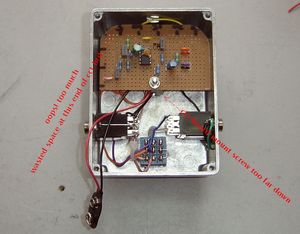
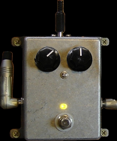
All done and looking good.... or is it?! Unfortunately when making this one I ignored my own advice and the circuit board sits too close to the sockets to accommodate the battery. The board should be sitting hard up against the top. I should have trimmed more off the top of the board where the texta marks are, as this is wasted space. Best to stick to the 40mm spec as in the case design! |
|
|
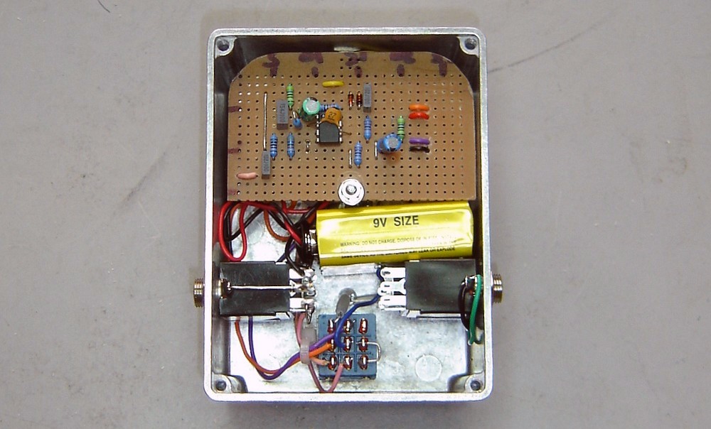
I fixed this by enlarging the hole in the board enough to move it up a bit. Not all that happy but it works... I can get the battery in & out reasonably easily. |
|
|
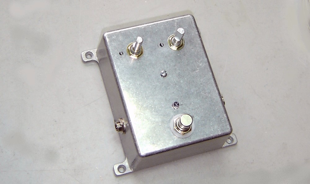
Almost done.. |
|
|
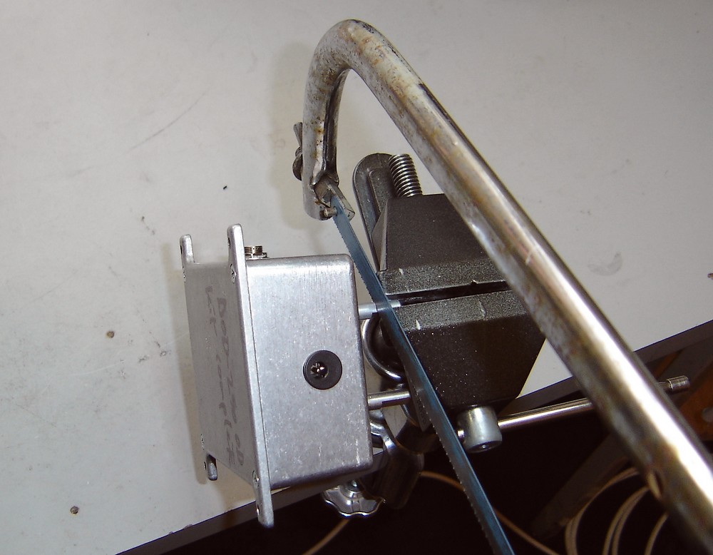
Now the pot shafts can be cut to the appropriate lengths to accommodate the knobs. This is done by holding the shaft in a vice, supporting the case in one hand so that there is no strain on the pot itself, and using a hacksaw gently saw through the shaft. This method stops alloy filings get into the electrical part of the pot and interfering with it's operation. |
|
|
| |
|
| |
| kelvin@guitars-of-love.com |