Guitars of Love
Japanese Retro - Tech
![]()
|
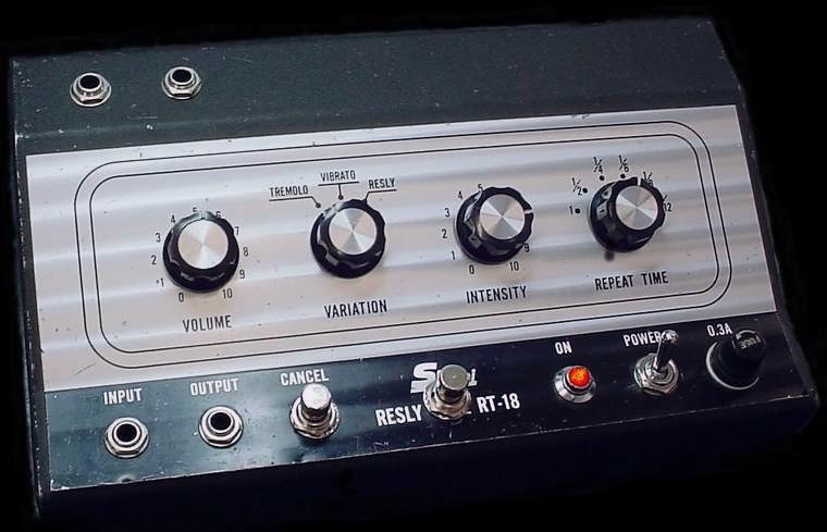
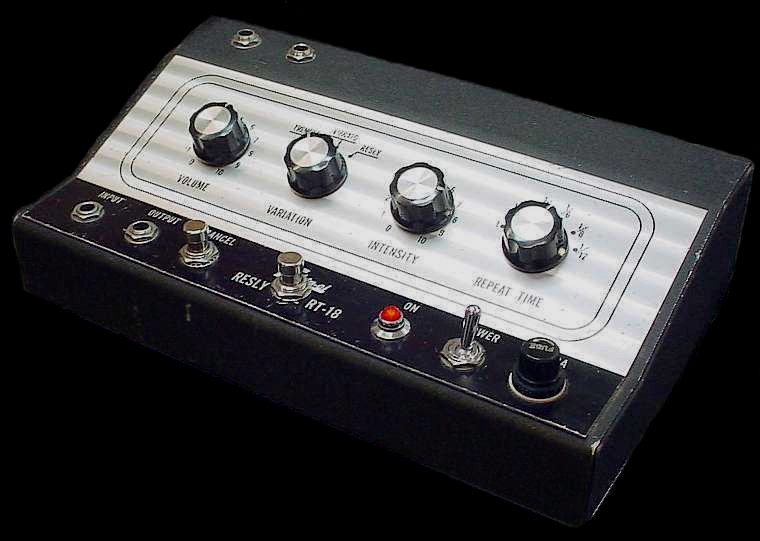
At right, a technological tour de force from the '60s. The Shin-ei RT-18 'Resly Tone' effects pedal. Utilising 4 light dpendent resistors (LDRs) and a light bulb driven from an astable vibrator / oscillator, this pedal produces three distinct types of vibrato. The 'Resly' effect sounds a bit like a Leslie Speaker used by Hammond organ players. In typically Japanese phonic style, they called it a "Resly" Instead of "Leslie" - or maybe they had copyright issues . A bit like the Mitsubishi 'Starion' car. It is (in my opinion) more transparent than virtually any modern tremelo pedal. It's just a pity it is so big & heavy! I mostly use the tremelo function so it's a pretty large gadget to cart around for this alone.
|
|
|
If you want to build your own tremelo based on the same principal, you might like to look at this one I have designed.
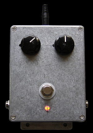
This new one of mine (I call it the 'Trembletone') emulates the same sort of operation as the Reslytone by activating a light source to an LDR, or ' light dependent resistor'. The new device just completed works perfectly, and produces no undesirable "pumping" in the speaker. The repeat rate goes from 1.5Hz to 15Hz, and has a fully variable intensity from zero to almost a full cut-off. The oscillator is an op-amp Wein Bridge oscillator driving the LED/ LDR via a Darlington transistor configuration. A great little project and cheap to make. It employs a true bypass stomp switch of course. |
 |
|
|
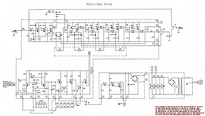
Although the Reslytone is all transistor, it's almost completely transparent - more so than many modern devices using ICs & transistors such as the famed Ibinez Tube Screamer and the discontinued Boss 'PN-2' Tremelo/ Pan pedal (pictured at left). These pedals suffer from the problem that including them in the signal path changes the sound of the guitar considerably even when switched to "bypass". The reason is because the buffer circuitry adds brittle sounding harmonics to the sound - and it shouldn't. That's poor design. The input stage has a very high impedance bootstrap configuration, and when the effect level "intensity" is turned down there is little discernible difference between the switched inputs. This unit is about 40 years old and still running fine. The only major drama which can occur is if the multipin connector to the main board fails. It is made of a type of plastic that will break down if any modern electrical lubricant or cleaner such as WD40 is applied. This happened to mine and it took several painstaking nights of circuit tracing to fix. Fortunately I had taken the trouble to trace out the complete schematic from a tiny copy which was pasted inside the unit to the inside of the case. A scanned pdf of the original schematic is here. |
|
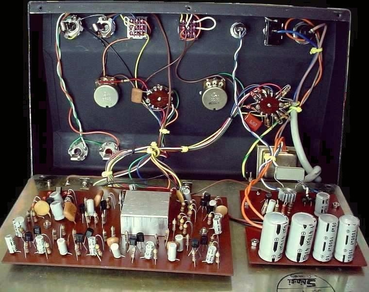
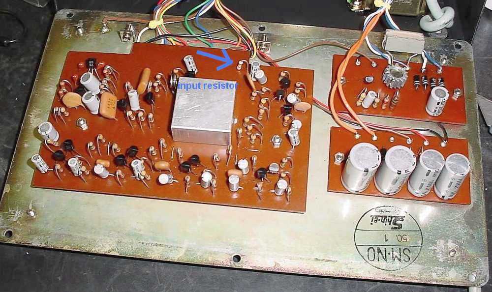
Photo of the insides, including the Kelvin mods. The photoelectric cells are located in the little metal box on the main board. My modifications entail a true 100% bypass arrangement involving two 9 pole stomp switches. The original circuit had the input hard wired to the input stage at 47K ohm impedance all the time which drained considerable volume and tone from passive vintage pickups. Because I use the Resly at the input from the guitar this is important. The mod gives an input impedance of 470K ohm when operating, but when switched out presents no load on the input. I have also included two other sockets (at the top of the unit) for a total bypass of all pedals using the Resly box to house this function rather than a separate box. |
|
|
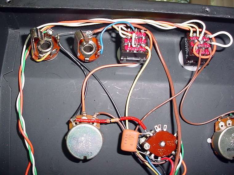
At right is a detail of the modern stomp switches, sitting next to the original in and out sockets. The mod for inputs and outputs can be found here. The mod for changing the indicator light to an LED can be found here. This involves making a simple an effective sub board (on vero board) which is much more reliable and efficient than the original. The original incandescent bulb is quite critical and if replaced with a different power bulb, does not work very well. The original design also drains some amplitude from the pulse signal due to the power hungry light. The full original circuit and the new modded one can be found here.
|
|
|
Below: The red arrow points to the input resistor. Originally 47K, this is way too low for passive PUs, and should be replaced with 470K - 1M ohm.
|
|
|
|
|