Guitars of Love
![]()
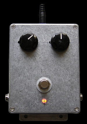
The GOL tremelo pedal - a beauty!
 |
kelvin@guitars-of-love.com |
|
I have been working on a tremelo circuit for a while....
|
This is a really good project for anyone wanting a good old fashioned tremelo pedal using the original optical coupling technology employed in such things as the Reslytone RT-18. I reckon it's pretty unique with what's around. There are any number of tremelo circuits on the net, but a lot them either don't work at all or not that well. I tried numerous circuits and then tried to effect a simplified version of the Reslytone RT-18. Although I got it working, I found that it relies on a number of combinations of resistors and capacitors switched in banks to give the very smooth waveform it generates from the astable vibrator circuit. I cannot decipher the part of the schematic that does this. It's just too ambiguous. After spending quite some time, I have a winner! The new circuit just completed works perfectly, runs on standard 9V DC, and produces no undesirable pumping because it uses an LED coupled to an LDR (light dependent resistor) to act as the variable volume control, just like the Reslytone RT-18. The repeat rate goes from 1.5 times a second to about 15 times a second, and has a fully variable intensity from zero to almost a full cut-off. The oscillator is an op-amp Wein Bridge oscillator driving the LED / LDR via a Darlington transistor configuration. The signal from the guitar only passes through a simple transistor / FET coupling circuit. The op-amp just supplies pulsing to the LED, and also supplies the indicator LED on the top of the unit showing both the frequency & intensity of the tremelo. It's a great little project for the tech inclined player, and cheap to make. It employs a true bypass stomp switch of course. I have designed the vero board layout which can be viewed here. I realise that there are any number of affordable whiz bang tremelos on the market which work perfectly. I have one - a Boss PN-2 (see left). My complaint is that it has no true bypass and when in straight mode, it changes the sound too much - makes it brittle. Things such as this sound great in the lounge room or music shop, but disappoint at a real gig. After a while you become aware that the guitar doesn't sound as rich as with it out of the setup. This ain't good enough for me. I'm a purest. Most of these devices use bog-standard op-amps to handle the audio signal which are a no-no in audiophile circles. For this reason I am thinking of turfing the occasionally used BOSS DD-2 out of my setup, or making a true bypass past it because I have noticed it dulls the sound compared to going straight into the amp. Simple class 'A' 'single ended' circuits using discreet transistors sound better than cheap op-amps, which are really class 'B' push-pull circuits. A push-pull circuit is most often characterised by bad harmonic characteristics due to the crossover distortion between the +ve & -ve halves of the circuit. The Shin-ei Reslytone RT-18 is a good example of an old circuit sounding better than contemporary ones. Really good op-amps cost a lot compared to the average two bob one, and FX manufacturers don't use the good ones in their pedals these days. I wonder sometimes whether designers actually listen to stuff any more. With the proliferation of mp3 and i-pods etc. I don't think folks are generally attuned to the subtleties. |
|
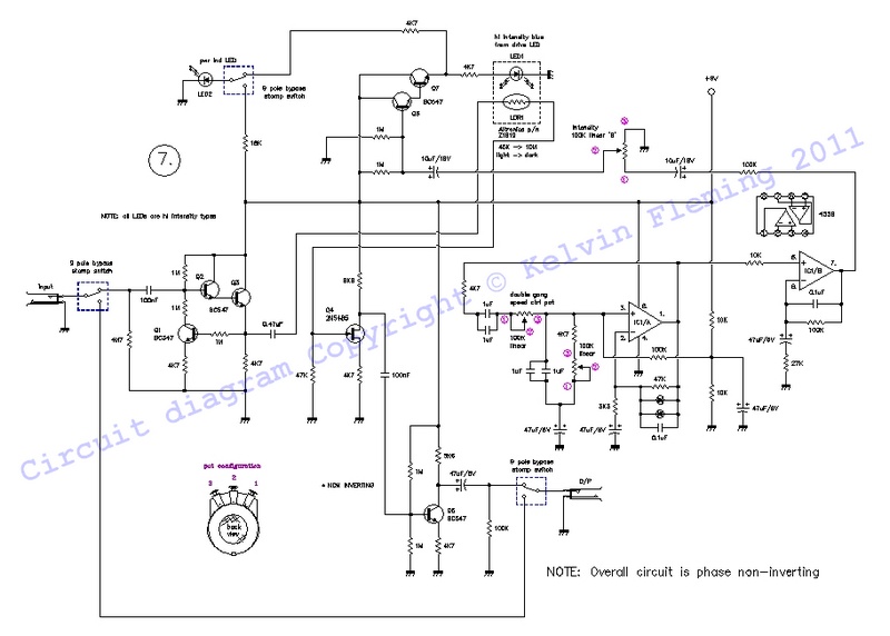
At right is the GOL Tremelo Version #2 schematic. Just click on the pic for the full res pdf version. Note that the repeat times can easily be changed or expanded by altering the capacitors/resistors in the Wein Bridge oscillator around the op-amp. e.g., the upper repeat limit is set by the R1 & R2 resistors, and can be increased by making these smaller (say) 3K3. the repeat time can be made longer by increasing C1/C2 & C3/C4. These are paralleled because I used MKT types which only go to 1uF. You could put 4.7uF electrolytics in for example, which would increase the repeat time to about 1. *** I have recently included a mod which puts a high value resistor (4.7 meg-ohm) just before the input 0.1 uF cap. This is to slowly discharge the +4.5 volts DC that occurs after switch on at the input cap to avoid a loud 'crack' when the unit is switched between the active tremelo and the passive bypass *** |
|
|
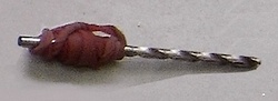
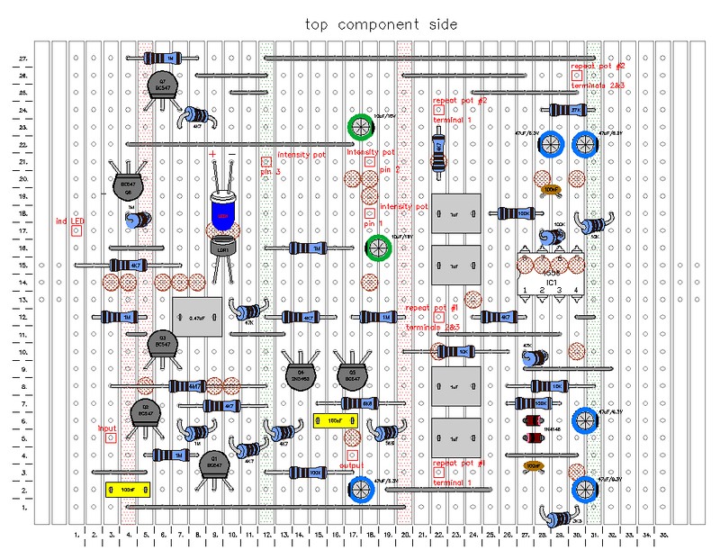
At right is a pdf graphic depicting the exact vero board layout. This is a very detailed diagram on pdf which shows you exactly where to put the parts, and break the copper strips in the appropriate places. It is an exact visual snapshot of a standard size 100mm x 75mm vero board available from many electronics stores such as Altronics. You can make it easier by marking out the rows and columns with a DVD marker. It is not an easy project and the wiring is a bit finicky. Note the the LED and the LDR (light dependent resistor) are enfolded in heat shrink. This just keeps the two parts snug together. you don't have to do this but I thought it made a neat job. The copper breaks are scalloped out with a 5/32 drill bit with a rubber band wrapped around as a handle.
|
|
|
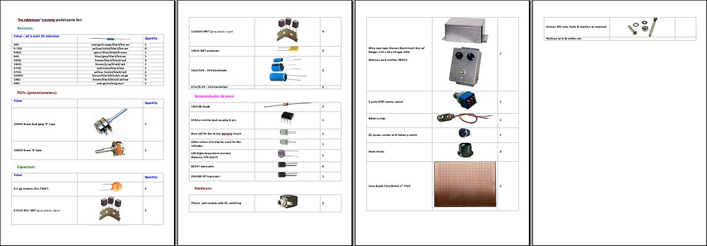
You can download the pdf parts list with pictures. Just click on the graphic at right: |
|
|
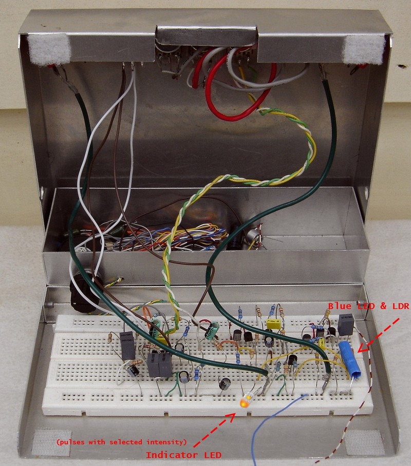
At right is the tremelo circuit set up on my little "breadboard" lab box. This is handy because it allows me to try it out under real conditions with a guitar and amp. |
|
|
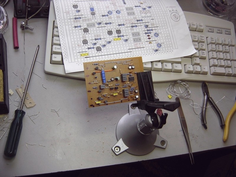
At right is the tremelo VII (1) board under construction (see below for re: VII(2). In the background you can see the vero board layout graphic: Click on the image to go to the higher res photos showing construction. All of these photos were actually taken during the building of VII (1) which had an overall inverting output. I decided to build another one with a non-inverting O/P with a slight gain overall (about 1 dB). VII (2) which is the one I use in my pedal rig, has some changes to the vero board layout graphic compared to the photos. |
|
|
|
|
| kelvin@guitars-of-love.com |